Support

CATEGORIES
How to install USA Deadbolt Smart Lock – Step by step
BLACK X Smart locks provide enhanced security and convenience, allowing you to control access to your home or office with ease. Whether you’re upgrading an existing lock or installing a new one, this guide will walk you through the process of installing a USA deadbolt smart lock efficiently and correctly.
By following these step-by-step instructions, you’ll ensure a secure and hassle-free installation. Let’s get started!
Step 1: Unbox and prepare components:
Open the packages and identify all components. Lay them out for easy access.
Hardware components:
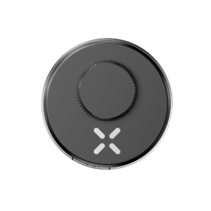
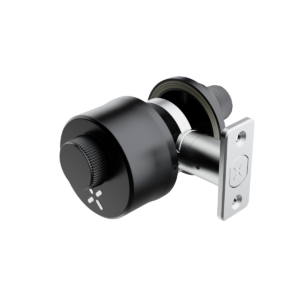
1X BLACK X deadbolt
Box 1:
- 1 x Mounting Plate: 2.75″ x 1.13″ (7 mm x 28.7 mm)
- 1x bolt extension cover
- 4x M5 x 1″ (25mm) Screws
Box 2:
- 1x CR2 3V battery
- 1x Allen key
- 1x screwdriver
- 2X mechanical key
(p)
Step 2: loosen the screws
- Use the provided Allen wrench and insert it into the screw socket as demonstrated in the video.
- Turn the Allen wrench counterclockwise to loosen the screw.
- Repeat the same process for the screw on the opposite side.
(p) (v)
Step 3: disassemble the BLACK X mechanism
- Rotate the BLACK X mechanism counterclockwise to loosen the body.
- Carefully separate the mechanism body and the ratchet housing, as demonstrated in the video.
(p) (v)
Step 4: Remove the Fasteners
- Insert the screwdriver into the designated fastener slots.
- Rotate the screwdriver to loosen and remove the fasteners from the component.
- Once the fasteners are removed, gently detach the components, following the directions demonstrated in the video, to fully separate the lock for assembly preparation.
(p) (v)
Step 5: Extracting the existing Cylinder:
- Use a screwdriver to remove the screws that secure the existing cylinder in place.
- Carefully pull the cylinder out of the mechanism.
- Measure the distance from the center of the lock to the edge of the door (see diagram for guidance).
(p) (v)
Step 6: Determine the Correct Fit for the BLACK X Deadbolt
Choose the appropriate cylinder length based on your measurement:
2.36” (60mm) or 2.75” (70mm)
Refer to the diagram for a clear comparison of the two sizes.
(p) (v)
Step 7: Install the Cylinder
Start with section 1 for the 2.75” (70mm) cylinder installation or Section 2 for the 2.36” (60mm) cylinder installation, as shown in the diagrams.
- Insert the Allen key into the designated screw slot and pull the bolt sleeve outward to extend the cylinder length.
- Use a screwdriver to rotate and pop the bolt face plate and bolt extension cover.
- Loosen the bolt extension cover with the Allen key and carefully remove it.
- Use a screwdriver to rotate and reinsert the base into its original position.
- Use the screwdriver to extract the metal pin.
- Slide the bolt component in the direction indicated in the diagram to ensure smooth movement.
- Insert the cylinder into the lock housing on the door, aligning it with the holes.
- Secure the cylinder by tightening the 2x M5 x 1” (25mm) screws.
- Use a screwdriver to reattach the metal pin.
- Rotate the bolt face plate back into position and pop the bolt extension cover.
- Place the bolt extension cover back. Note: Select the appropriate size of the bolt extension based on the required lock length.
- Tighten the bolt extension cover using the Allen key.
(p) (v)
Step 8: Installing the CR2 battery
- Use a flathead screwdriver to open the dual-function battery compartment cover. Turn the screw half a turn and press down on the latch to release the compartment.
- Insert the battery release tab into the lock. Place the CR2 battery into the BLACK X device, ensuring the positive (+) and negative (-) ends align with the symbols on the battery pull tab. A beep will confirm the device is operational.
- Return the battery compartment cover to its original position with the tab facing outward from the lock. Use the flathead screwdriver to turn the screw back to its locked position.
Step 9: Attaching the BLACK X Deadbolt Device
- Insert the lock mechanism through the door as shown in the diagram.
- Align the components with the corresponding holes on both sides of the door.
- Slide the lock mechanism fully into place, ensuring it fits securely within the door structure.
- Tighten the screws to secure the lock in place and ensure proper alignment and functionality.
(p) (v)
Step 10: Identifying Door Orientation
- Determine Door Opening Direction:
Check the position of the hinges to identify if the door is left-handed or right-handed:
-
- If the hinges are on the left, the door is left-handed.
- If the hinges are on the right, the door is right-handed.
- Mark Orientation:
Use the red marker for left-handed doors and the green marker for right-handed doors (see diagram for reference).
(p) (v)
Step 11 : Pairing with the BLACK X App
- Open the BLACK X App.
- click on ‘install a new lock’.
- Name Your Lock or choose a description.
- Create a ‘Home’ to associate with your lock.
- Choose the ‘Home’ for your lock.
- While in “Discovering Nearby Locks” mode, use the Allen key to press the connect button on the BLACK X device.
- When a pop-up for the correct lock appears, click “Connect” to proceed.
- Congratulations! You’ve successfully connected your first lock.
(p) (v)
Step 12: Final Assembly
- Align the two parts of the lock assembly, as demonstrated in the video.
- Rotate the assembly in the direction indicated by the red arrows to securely connect the components.
- Once aligned, ensure the mechanism locks into place by rotating it slightly to confirm a tight fit.
- Use the Allen key to rotate the screws clockwise and tighten them on both sides.
(p) (v)
Step 13: Operational Settings and Optional Wi-Fi Bridge Setup (if purchased)
- Functionality Test: With the door open, use the BLACK X app to activate the unlock command and verify that the device operates correctly.
- Optional Wi-Fi Bridge Installation: If purchased, connect the USB-C Wi-Fi bridge to enable remote access features.
(p) (v)


